
As announced in my previous article, where I had introduced Flow Design, I want to show a concrete implementation in Java. The code for this example may be found on GitHub.
I will follow the blog article “IODA Architecture by Example” of Ralf Westphal which made a Flow Design and implementation for the following scenario:
Build an application that translates a Roman number entered by the user into an Arabic number and vice versa.
It may be valuable to read his article too, to get further details. However, I will repeat his steps (sometimes a little bit shortened) for letting you get the whole picture. Nearly all drawings are originated from Ralf’s blog.
Requirements Analysis
Analyzing the scenario description, there must be an application the user is able to type a Roman or Arabic number in. As nothing specific is required, a simple console program may satisfy this requirement.
This could be look like:
> convertroman XIV
14
> convertroman 42
XLII
>
There is nothing stated about validation. So the validation will be a very basic one.
Solution Design
Of course, we do not make object oriented design here. We have another intention. Flow Design is the goal. So, we start with the top level abstraction. All what we know from the requirements analysis is that the “world” starts triggered by the user: the user starts the program. In Flow Design this may be represented as:
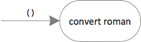 This is the highest level of abstraction.
Flow Design
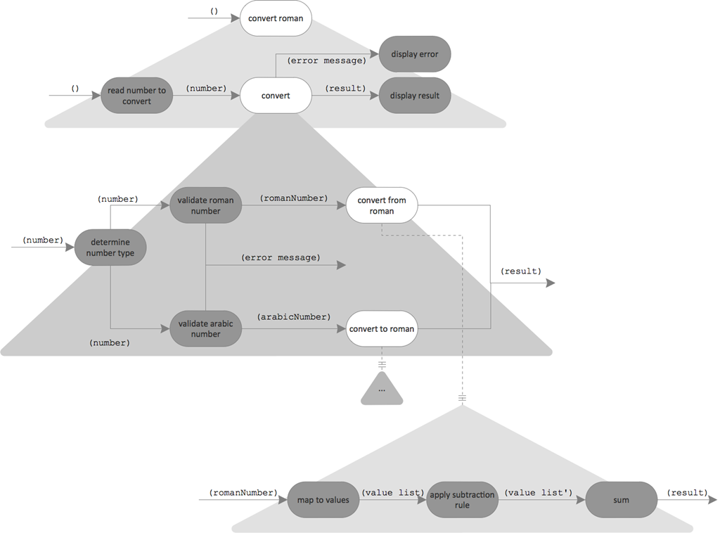
Now the “parts” (aka functional units) come into play. The next design step is to figure out, which processing steps build the root part on the highest level of abstraction. The functional unit “convert roman” becomes the root of an integration hierarchy.
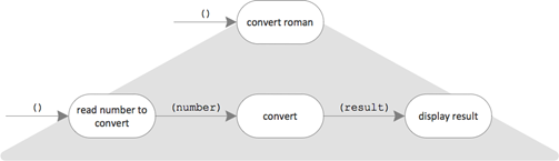
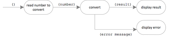
For the functional units in the picture above, the two outside ones are quite truly understood. Reading in input from the command line and displaying a result of characters on the same is easy to implement. However, the functional unit “conversion” is not so clear. Further refinement is needed.
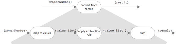
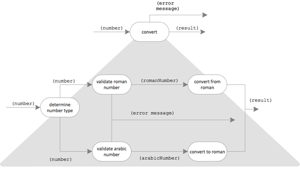
Until now, “conversion” was an operation. But now it is opened up and becomes an integration unit wiring up more fine granular operations. Here also the validation should have its place. Let’s put the pieces together:

- Each roman digit of Roman number is translated into its value. The result is a list of integer numbers. E.g., “XVI” -> [10, 5, 1].
- In case, a smaller value is coming prior to a larger value in the list, the smaller value is negated. E.g., [10, 1, 5] -> [10, -1, 5]. In the original article called “applying subtraction rule”.
- The values are accumulated to calculate the sum of them. E.g., [10, 5, 1] -> 16
Wiring these 3 steps together forms the following “domain process”:
Data Design
The [I]ntegration and [O]peration entities of the IODA architecture have been setup. The [A]PI going to be used is not really worth to be mentioned; it’s obviously the Java language framework. However, the [D]ata still needs to be designed.
The data types are already in the Flow Design diagram and might be read out. Here, they come extracted:
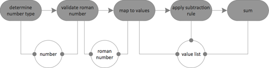
The connections from functional units to the data types have a filled circle at the end. That’s how dependencies are marked in Flow Design. So, dependencies are not out of scope here. However, they are restricted to those cases where they are natural
- functional units are depending on data types they receive or send; and
- functional units may depend on units holding state (e.g. database access)
We do not have state in our design. But data types are there. For those, object oriented design would be an appropriate tooling if they are not trivial. However, following the KISS principle, we do not introduce specific types for the domain concepts roman number and arabic number. The first one is just a character string, the second one an integer. There is just no value in designing specific types if it may also be done with the ordinary Java types. A value list might be quite easily represented by an integer array or Java List.
Anyway, the design decision on data types made here does not change the basic architecture. Operation units work on data. So, if the data design gets changed, they are mainly influenced by that.
Class Design
As we are going to implement the set up design in Java, we need to think about classes as they are one of the main code building blocks of object oriented languages. The code building blocks form a hierarchy in the design dimension of modules starting from methods or functions as the smallest kind of code module, followed by classes, packages, libraries, components and micro services.
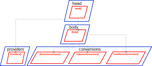
The difference to Object Oriented Design comes up here quite obviously: We do not start thinking first about classes; no need to come up with “candidate classes”. We think about behavior/functions first. The classes are just derived directly from the patterns seen in the Flow Design. The bubbles are grouped into classes as follows:
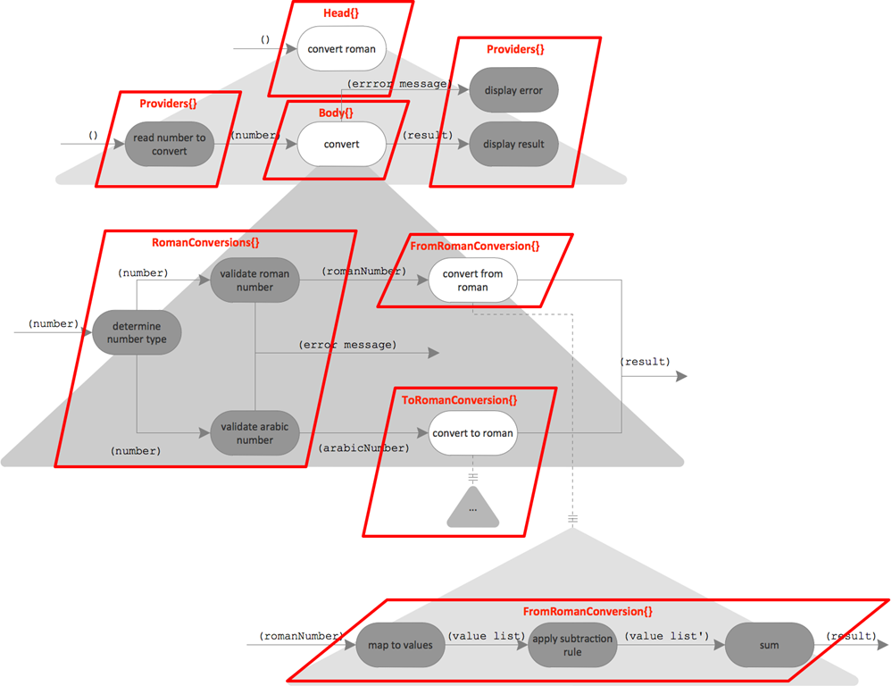
Not all of those classes are obvious. Ralf Westphal explains his grouping decision as follows:
- Providers: Using an API is a “hard” aspect in any software. It should be isolated into specific modules. Usually, each API should be encapsulated by its own class – but in this scenario there is so little of it, a single class will do.
- FromRomanConversion and ToRomanConversion: Doing the actual conversion is an aspect of its own. Since there are two directions of conversion a module for each seems to be in order.
- RomanConversion: This class belongs to the coarse grained domain aspect of the application. It contains “helper functions” not actually concerned with the transformations.
- Body: This class represents the overall functionality – but without the interaction with the user. It’s like an internal API to what the program is supposed to do.
- Head: The head is responsible for triggering body behavior. It integrates the body with input from and output to the user.
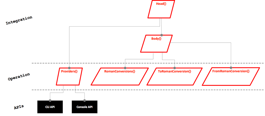
The class diagram follows the IODA architecture; integrations, operations, and API are recognizable. Only the data is missing as the scenario is so simple that no data types has been designed:
Interfaces and Static Methods
There is more to decide at class design. In particular, we need to know which classes will get instantiated and which one became a code container for static methods only.
As there is no state involved, RomanConversion, FromRomanConversion, and ToRomanConversion do not need to be instantiated. Their contained methods could be static.
For Provider it looks different. The Interface Segregation Principle gets applied here as API access is going to be implemented. Therefore, Head also requires getting instantiated.
Also Body is described as an interface to allow Head being tested in isolation.
Package Design
The next level in the hierarchy of code modules are Java packages. This is quite Java specific, the original design article do not have it as C#’s language concept of namespaces is not a so strong code structuring tool as Java’s packages are. Java’s packages are quite stronger as they define the visibility of classes and methods.
Structurally, my package design is quite similar to the original article’s library design at its leafs.
- conversions contains all classes of the business domain
- providers has all classes in dealing with the APIs
- head is the home of the top level integrator
- body contains classes responsibly of the integration of the “backend”; here, the behavior is created
However, I have introduced another level of grouping. I put all packages containing operation classes under the sub package operations, all classes which are doing integration into the sub package integration. Finally, I have also a package contracts. It contains all the interfaces designed.
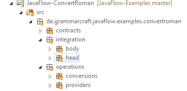
All packages are prepended by the name space prefix de.grammarcraft.javaflow.examples.convertroman for uniqueness.
Library Design
Organizing code into libraries is the next tool in building a module hierarchy. In Java this is normally mapped to JAR archives.
It is quite worth to think about that during a design, as it is typically the smallest deployment artifact. At this level functional extensions and bug fixing may be applied to already roll out solutions ensuring evolvability of that solution by replacing libraries. Especially, in distributed environments libraries are the cutting points for code forming the distributed modules landscape.
As this solution is quite simple, there will be only one library at all, one JAR file.
Component Design
Ralf Westphal defines the term component as a set of one or more libraries, described by a platform specific contract. Think of a component like a bundle of JAR files with a facade as entry point, or like an OSGi bundle.
Structuring the code into components, boundaries of which are determined by contracts like interfaces or facade classes are a precondition of professional software development. At least, it helps a lot in teams developing in parallel. Each team member is developing one component under the head of the contract of its component applying other contracts of foreign components maybe not ready yet.
Implementation
The implementation is done straight forward. Here is the resulting project structure in Eclipse:
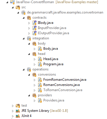 You may view the source project on Github.
Let’s take a closer look on how split flows had been implemented in Java. Now, we can take advantages of the new Java language feature of lambdas, which are making the implementation really concise; at least as concise as it is possible in Java currently, as Java does not allow to setup internal DSLs.
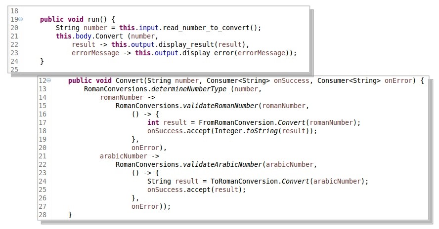
Looking at the code above, you might need a minute to understand what is going on. However, it is just a straight forward implementation.
Lets take the topmost flow.
Which results in the the already shown source code below:
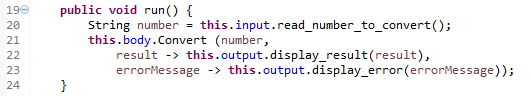
Just read function calls from top to bottom and left to right. Indentations are different paths in the flow.
In fact, each bubble in the diagram translates to a method call. If a bubble has one output, the function simply returns it. If a bubble has more than one output, they are implemented as continuations – function objects predefined in Java as Consumer taking the data type as generic parameter. So, the implementation gets type safe.
Those continuations are what make the code a bit hard to read. But only at first. It’s unusual, not wrong. You just have been trained for so long to read nested function calls from right to left and inside-out; but once you get used to continuations you’ll come to appreciate how easy it is again to read code. [Ralf Westphal]
Conclusion
I have shown that the implementation of an IODA Architecture based on a Flow Design is as easy as Ralf Westphal showed in his article for C#. In fact, that was not surprising as with the lambda language concept Java gets similar powerful as C# with its delegates and lambda notation.
However, it is still somewhat difficult to read the flow in the Java or C# implementation. What, if we could specify the flow in integration units directly as follows:
![]() You may not get closer to the intentional flow design diagram. That would significantly increase readability, isn’t it?
You may not get closer to the intentional flow design diagram. That would significantly increase readability, isn’t it?
Such notations are possible, even on the JVM, if you are using programming languages which allow the implementation of internal DSLs. I will show in the next article how this may be done in Scala and Xtend. I will implement the same example of converting Roman numerals to get it better comparable.
If someone already wants to take a look forward, it’s already implemented at the following GitHub projects:
Stay tuned.